METALARTDESIGN / RHINO ADD-ON

Your model.
Your parts.
All connected.

From a 3D model to organised laser-cut parts. Prepare sheet-metal parts directly in Rhino – with matching joints, clear numbering and cut data you can check.

Developed for Rhino 7 on Windows
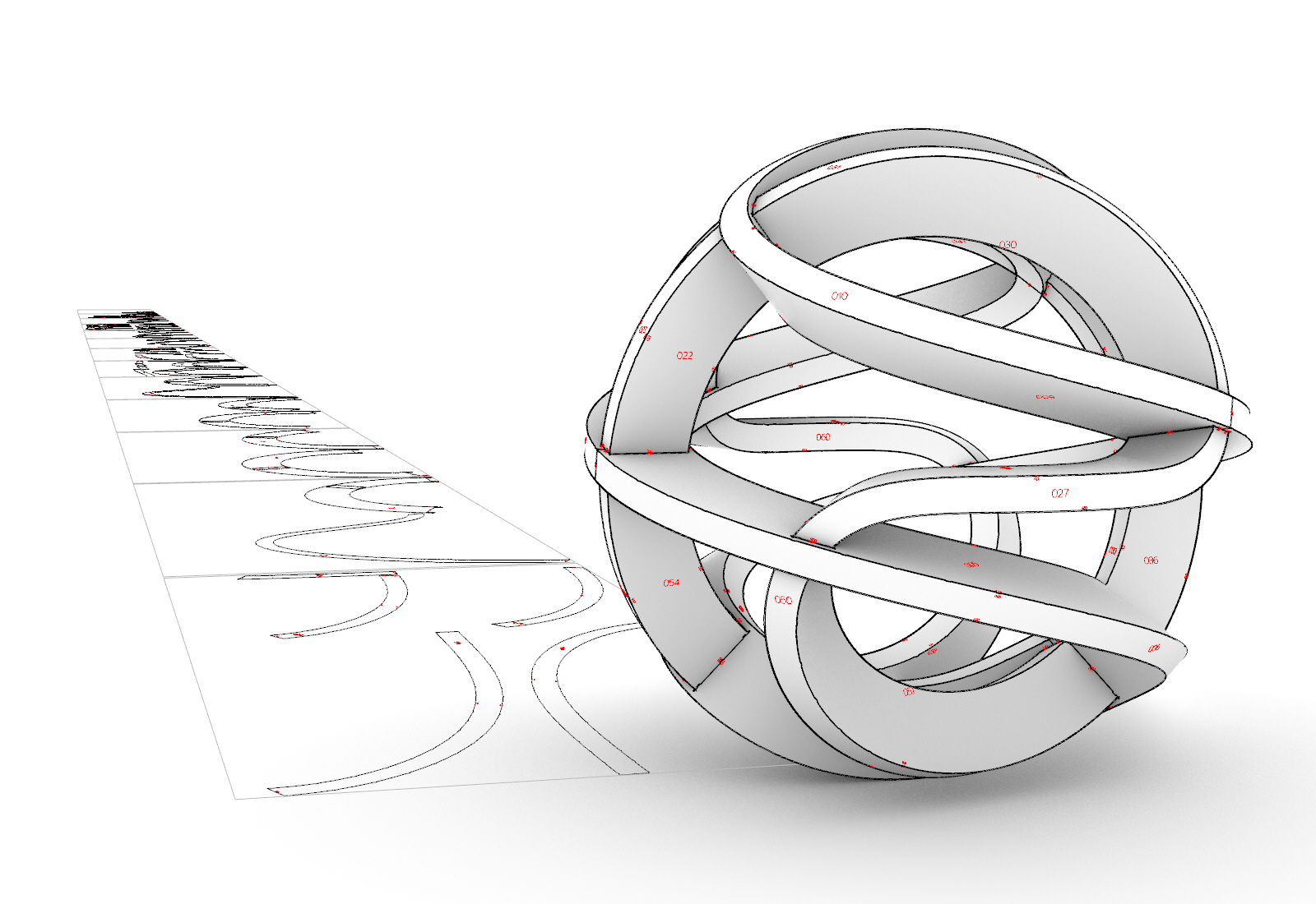
Rhino model of a spherical sculpture made from curved sheet-metal parts on the right, with the corresponding flat cut parts on the left. Red numbers identify the parts.
Curved sheet-metal parts in the 3D model and their corresponding flat cut parts.

In development

Your ideas are welcome

Rhino Laser is still in development and has not yet been released. No release date has been set yet.

Do you have questions, suggestions or an idea for a useful feature? Feel free to email me. I welcome practical ideas that can help shape the tool's further development.

Questions & ideas by email

01 Directly in Rhino

02 Identify parts & partners

03 CUT + ENGRAVE in DXF

01 / THE TOOLS

From your design to the
very last part number.

Geometry, joints and labels in one workflow. Turn individual contours into parts that belong together.

01 — DIVIDE

Prepare sheet-metal parts.

Merge suitable surfaces and deliberately choose where to split them. Material thickness and surface orientation provide the foundation.

02 — CONNECT

Joints that fit.

Butt joints, rows of tack-welding holes or rectangular tab-and-slot joints. With adjustable spacing, corner webs and clearance.

03 — IDENTIFY

Every part knows its partner.

Part numbers and partner numbers at the joint edges. Engraved, with a selectable sequence and your own part groups.

04 — UNROLL

Designed for curves, too.

Unroll suitable curved sheets and strips. Check values reveal joint deviations and changes in length.

05 — ARRANGE

Your sheet. Your layout.

Set the sheet format, margin and part spacing. Compare layouts and use multiple sheets with 90° rotations when needed.

06 — HAND OVER

Cut data with the full picture.

One DXF per sheet, with separate cutting and engraving layers. Plus quantities, weight and check reports – optionally as a readable PDF report.

02 / THE DETAILS MAKE THE DIFFERENCE

Fit together.
Find each other.

The joint determines the contour. The labels make the connection clear – on the flat cut part and in the 3D model.
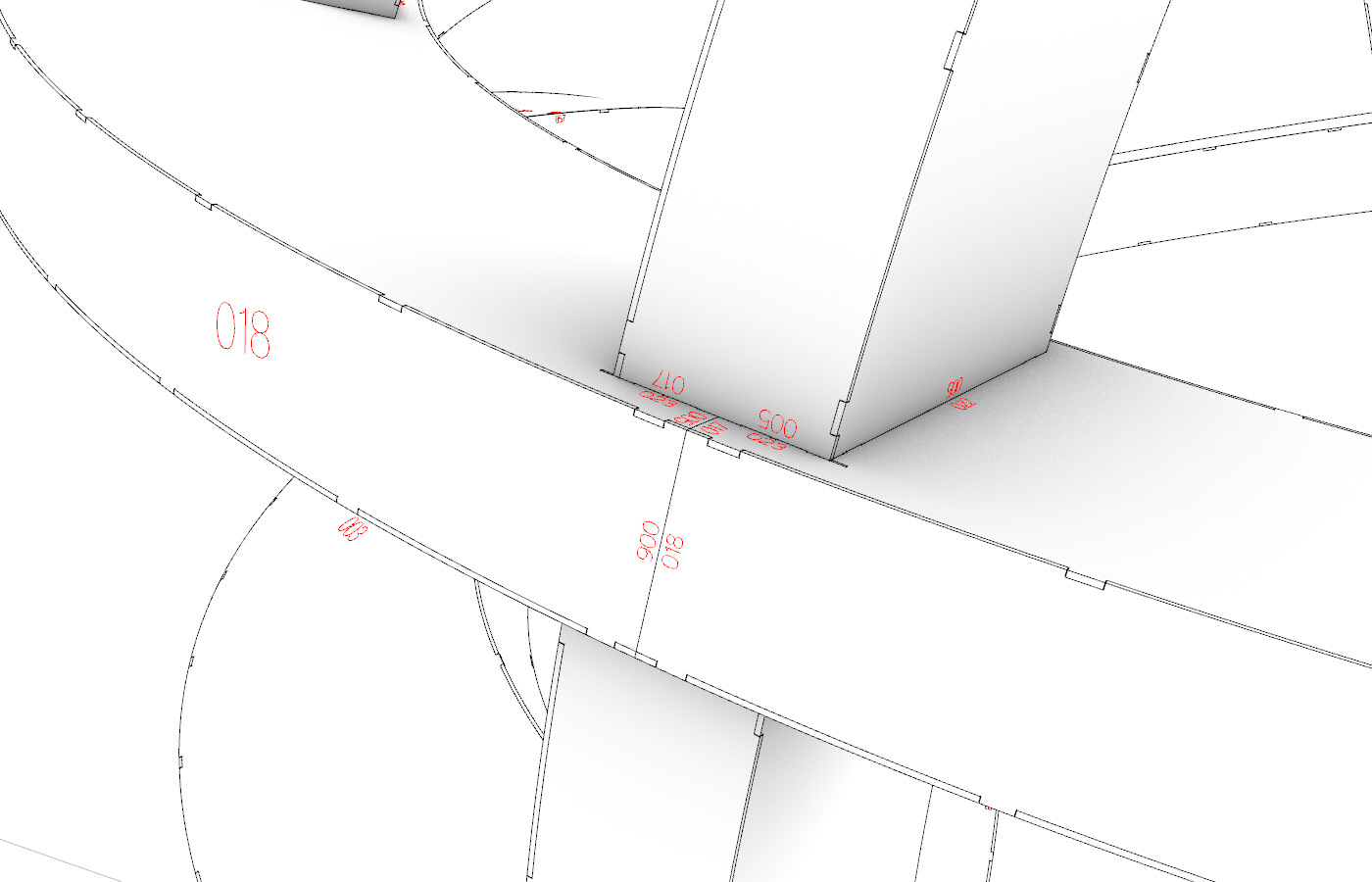
Close-up of connected sheet-metal parts in the Rhino model: rectangular tabs and slots at the joint edges, with red part and partner numbers.
01

Geometry that belongs together.

Tabs and slots are calculated as matching pairs. Thickness, angle and total clearance determine the joint. Small areas can intentionally be left without notches.
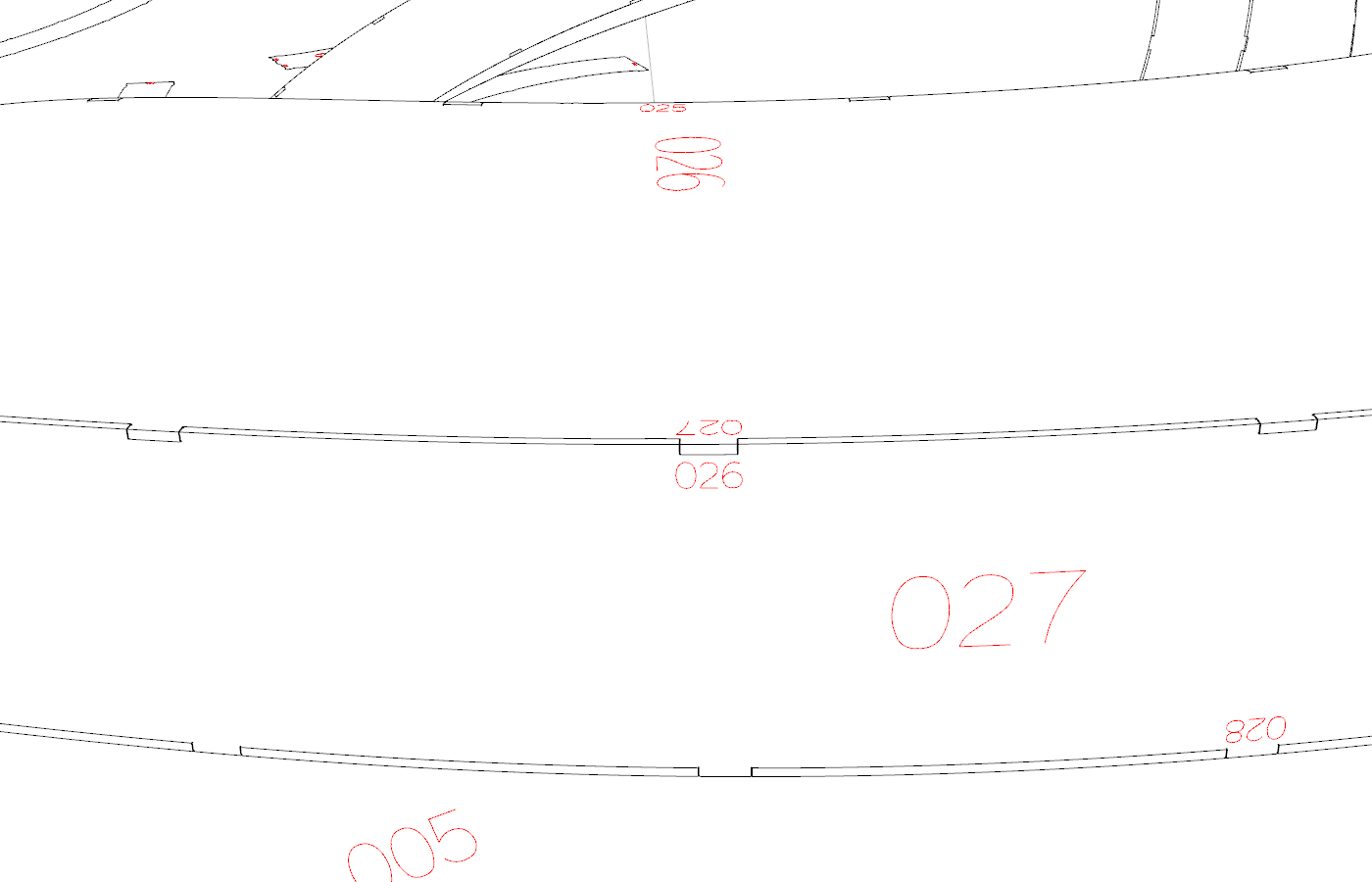
Sheet-metal parts with large red part numbers 026 and 027 on their faces and smaller partner numbers along the shared joint edges.
02

Not just numbered. Matched.

The part number tells you which sheet-metal part you are holding. The partner number tells you which other part connects to this edge.

03 / YOUR WORKFLOW

One model.
A clear path to cutting.

Stay in Rhino. Your original model is preserved; the results are created on separate output layers.

  1. 01

    Prepare the model

    Select the geometry, define the sheet divisions and set the material thickness.

    PREPARE
  2. 02

    Choose the joints

    Set the joint type, clearance and spacing. Define the sheet format and layout.

    PREPARE
  3. 03

    Label the parts

    Engrave part and partner numbers. Adjust the sequence and part groups.

    ASSIGN ENGRAVING
  4. 04

    Check & export

    Compare 3D and 2D, review warnings, and export DXF files with reports.

    RESULTS & EXPORT

04 / STEP BY STEP

Try it.
Understand it.
Build on it.

Start with a simple box. Then add joints, numbers and your own sheet layout.

A good starting pointA separate Rhino document, millimetres as the unit and a clearly structured model.

Instructions for the documented development build. Before manufacturing, adapt the example values to your material and process.

English and Spanish are planned for the plugin. Menu images in these languages are translated illustrations; the current application interface is still in German. Names in quotation marks refer to the current German controls.

TUTORIAL 001 · VIDEO

From 3D model to laser-cut part

Video in German

The workflow on video: prepare the model, configure joints, label the parts and export the cutting data as DXF.

Watch on YouTube
01Install & open the panelGetting started with RhinoLaser
  1. Place the complete RhinoLaser package folder in a permanent location. Keep all files together.
  2. In Rhino, use RunPythonScript and select Install_RhinoLaser.py from this folder.
  3. Use RhinoLaserPanel to open the panel. The three tabs are “Vorbereiten” (Prepare), “Gravur zuordnen” (Assign engraving) and “Ergebnis & Export” (Results & export).

Check: The panel is visible and you can still use the model view. This setup applies to Rhino 7 on Windows.
02Your first boxFrom test model to six sheet-metal parts
  1. Open a separate Rhino document in millimetres. Use a document tolerance of 0.01 mm for this example.
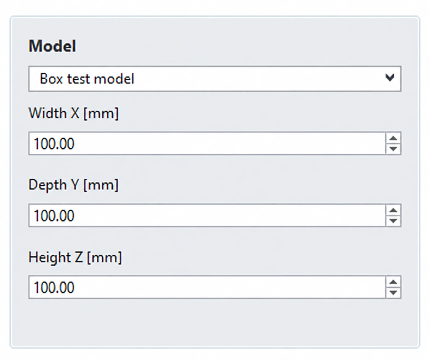
  2. Under “Vorbereiten”, select “Quader als Testmodell” as the model. Leave the dimensions at 100 × 100 × 100 mm.
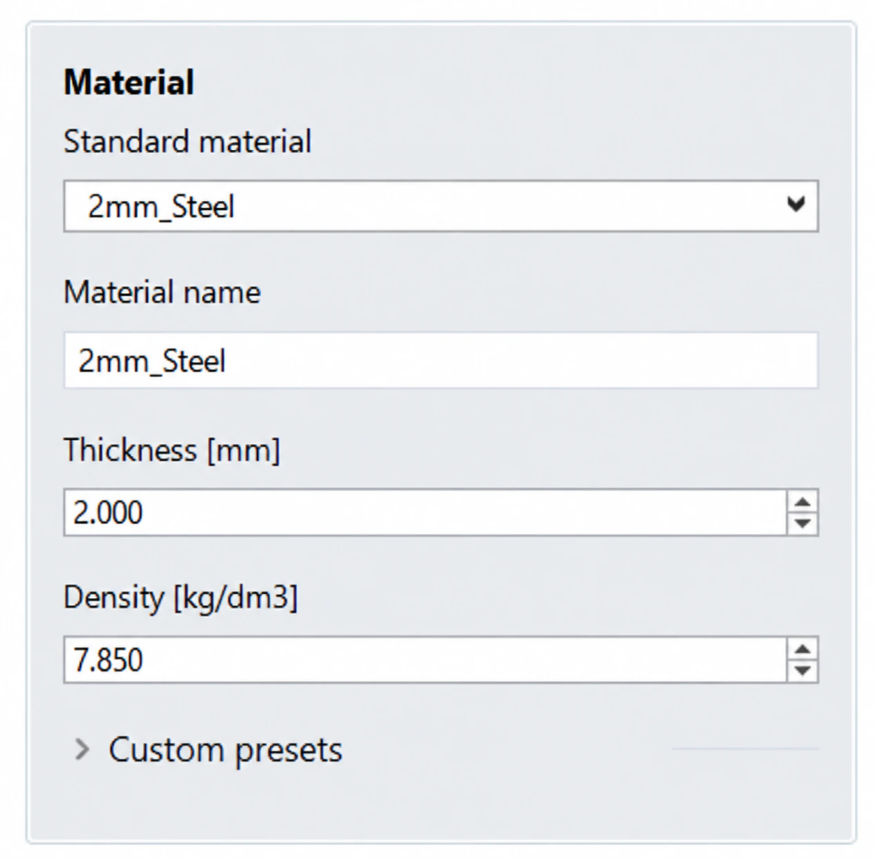
  3. Choose a material thickness of 2 mm and “Kantenstoß” (butt joint). Leave the 3D material preview enabled.
  4. Initially disable laser engraving. This keeps your first test independent of any installed engraving font.
  5. Choose “Schnittteile erzeugen”. Select a part in the result and compare its 3D and 2D representations.
Translated illustration: RhinoLaser model settings: box test model with width X, depth Y and height Z each set to 100 mm.
Translated illustration Box test modelIn this example, width X, depth Y and height Z are each set to 100 mm.
Translated illustration: RhinoLaser material settings with the 2mm_Steel preset, a thickness of 2 mm and a density of 7.85 kg per cubic decimetre.
Translated illustration Select the materialPreset shown: “2mm_Steel”, with a thickness of 2 mm and a density of 7.85 kg/dm³. You can set the material name, thickness and density here.

Check: Six sheet-metal parts are created. The 2D layout appears to the right of the model. Material and joint corrections may change the individual cut dimensions.
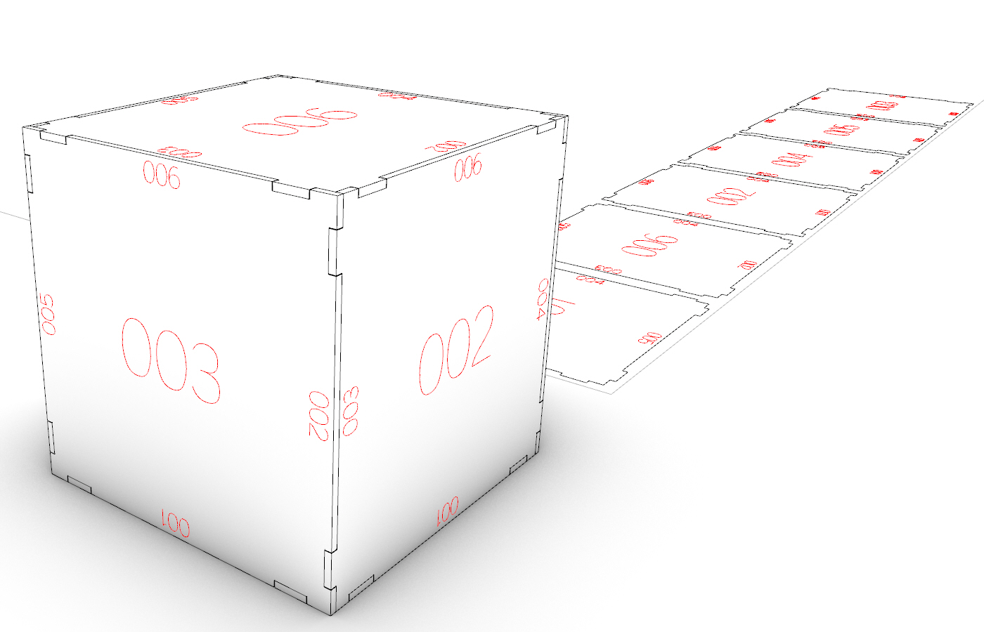
Box made from six sheet-metal parts with rectangular tab-and-slot joints and red part and partner numbers on the left; the corresponding flat cut parts are arranged to its right.
After the next tutorials: a box with tab-and-slot joints and numbers, alongside its flat cut parts.
03Rectangular tab-and-slot jointsUnderstand tabs, slots and clearance
  1. Keep the box output loaded and choose “Rechteckige Steckverbindung”.
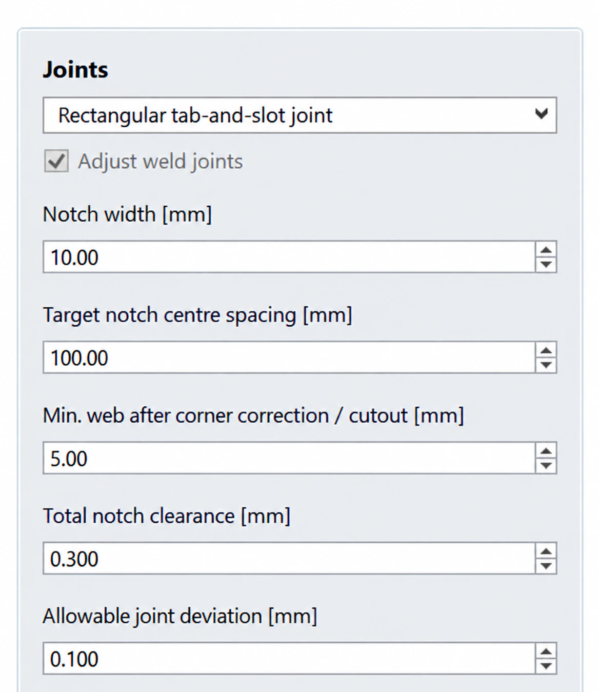
  2. Check the example values: notch width 10 mm, target spacing 100 mm, minimum web 5 mm and total clearance 0.3 mm.
  3. Leave “Kleine / schmale Bleche ohne Kerben” enabled and choose “Schnittteile aktualisieren”.
  4. Zoom in on both sides of a joint. Under “Prüfung und Hinweise”, look for short or small joints without notches.
Translated illustration: Rectangular tab-and-slot joint settings: notch width 10 mm, target spacing 100 mm, minimum web 5 mm, total clearance 0.3 mm and allowable joint deviation 0.1 mm.
Translated illustration Set up the jointExample values: notch width 10 mm, target spacing 100 mm, minimum web 5 mm and total clearance 0.3 mm. The allowable joint deviation is set to 0.1 mm.
10.0 mm slot− 0.3 mm total clearance= 9.7 mm tab

Important: Here, the total clearance corresponds to 0.15 mm on each side. This is not automatic kerf compensation for the laser machine.
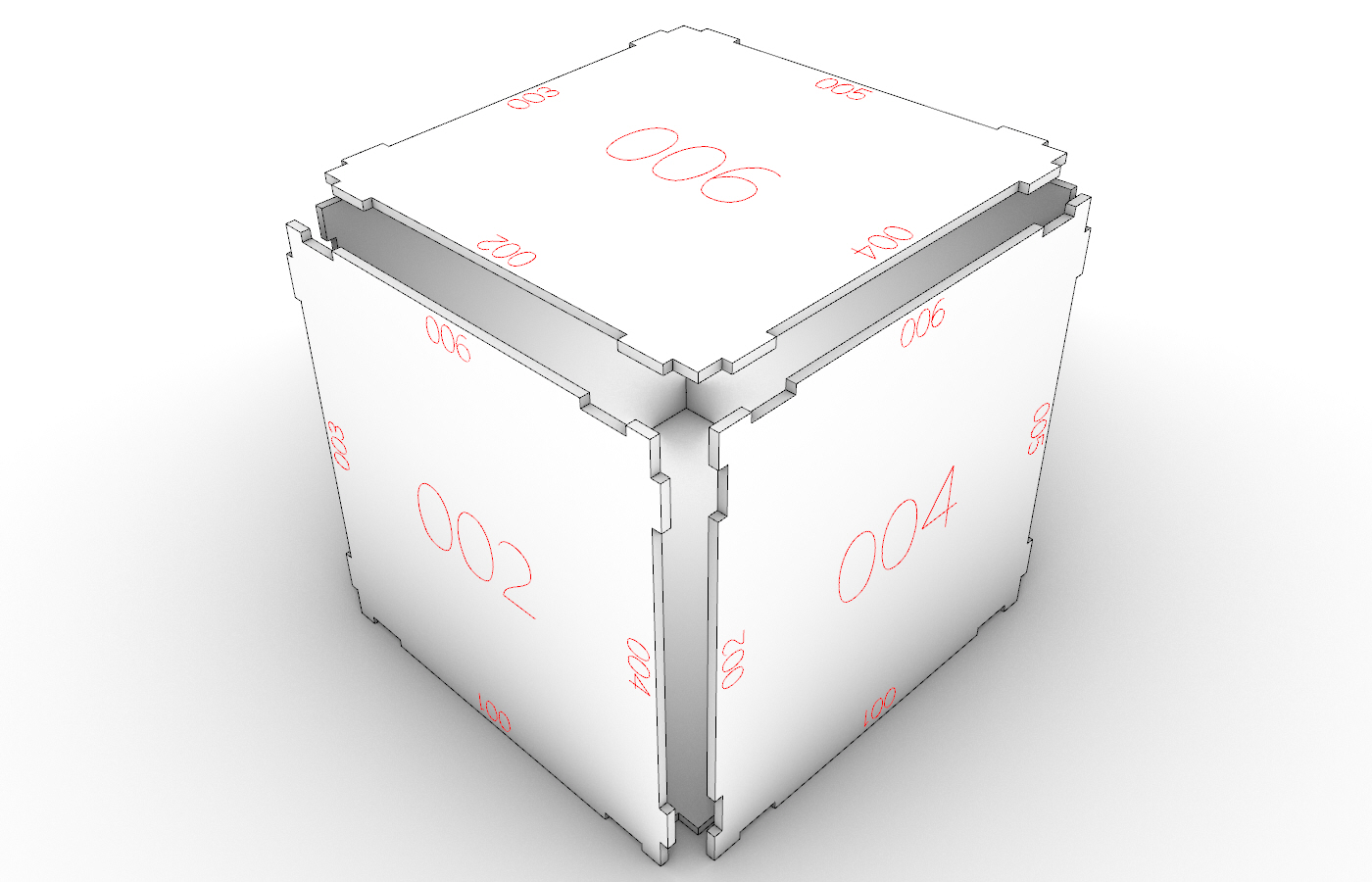
Faces of a sheet-metal box manually pulled apart for illustration, showing rectangular tab-and-slot joints and red numbers; not a model preview generated by RhinoLaser.
The faces were manually pulled apart for this image to make the tab-and-slot joints visible. This is not the preview model generated by RhinoLaser; the gaps do not represent the configured joint clearance.
04Engrave part & partner numbersIdentify connections directly on the sheet
  1. Under “Gravur zuordnen”, enable laser engraving and select an available font. “SLF-RHN Architect” is intended for single-line engraving.
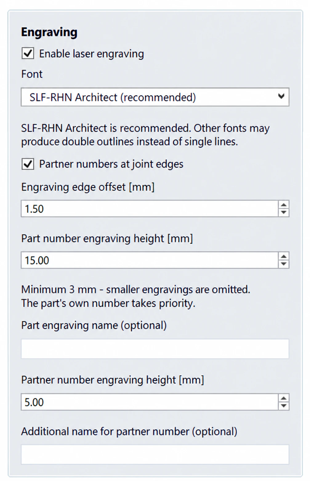
  2. As a starting point, try 15 mm for the part's own number, 5 mm for partner numbers and a 1.5 mm edge offset.
  3. Enable “Partnernummern an Anschlusskanten”. Optionally enter an additional name, for example “Project”.
  4. Update the output. Select a part and distinguish its own number from the numbers of its neighbours.
  5. Show the 3D engravings and check the material side and reading direction.
Translated illustration: RhinoLaser engraving settings: laser engraving and partner numbers enabled, SLF-RHN Architect font, edge offset 1.5 mm, part number height 15 mm and partner number height 5 mm.
Translated illustration Set up engravingLaser engraving and partner numbers are enabled. In this example: part number height 15 mm, partner number height 5 mm and edge offset 1.5 mm.

If space is limited: The part's own number takes priority and may be reduced in size. Below 3 mm, the engraving is omitted and reported. Other fonts may produce double outlines.
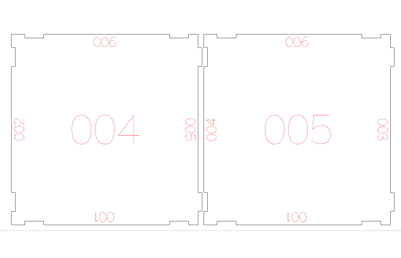
Two flat cut parts with large red part numbers 004 and 005. At the joint edges facing each other, part 004 carries partner number 005 and part 005 carries partner number 004.
Large on the face: the part's own number. Small at the joint edge: its partner – here, 005 on part 004 and 004 on part 005.
05Sequence & part groupsNumbering that follows your project
  1. Load an output. Under “Gravur zuordnen”, choose a numbering method: model order, world Z, manual, groups from left to right or spiral.
  2. For a custom sequence, choose “Ohne Bauteilgruppe” and “Teile manuell nacheinander anklicken...”.
  3. Click the parts in the desired order and confirm with Enter. “Rückgängig” undoes the last selection step.
  4. For separate letter groups, choose “Neue Bauteilgruppe” and assign parts to the selected group.
  5. Choose “Schnittteile aktualisieren” so that engravings and reports reflect the new assignment.
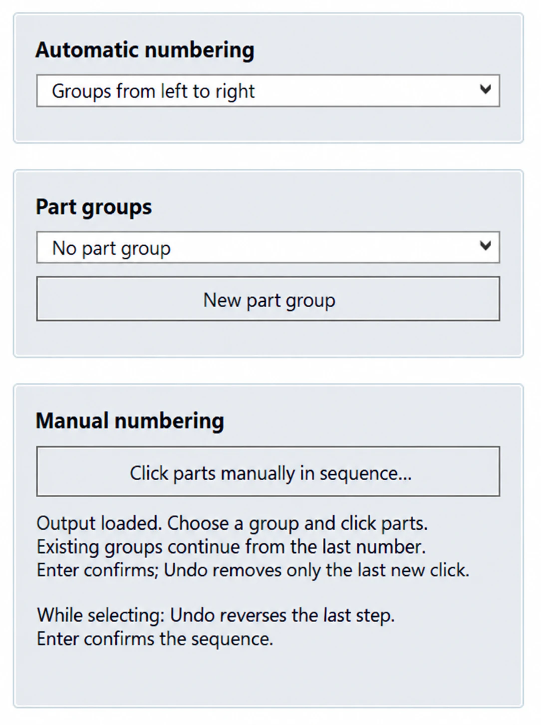
Translated illustration: RhinoLaser numbering with groups from left to right, the no-part-group option and buttons for new part groups and manual numbering.
Translated illustration Sequence and groupsThe image shows “Groups from left to right” selected. Below, you can create part groups and click parts in sequence for manual numbering.

Check: Part and partner numbers match. When using spiral sorting, check any reported transitions without a shared edge.
The five original Rhino solids forming the word RHINO, without part or partner numbers.
01 · Original solids: the five letters of RHINO, before adding part and partner numbers.
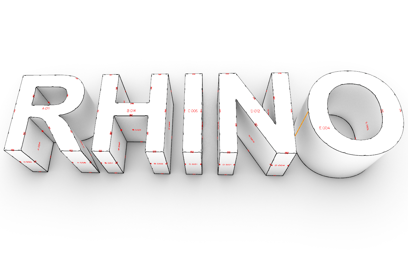
RHINO lettering with assigned part groups: R belongs to A, H to B, I to C, N to D and O to E. Red part and partner numbers identify the sheet-metal parts.
02 · Groups assigned: in this example, R, H, I, N and O belong to groups A, B, C, D and E. The sheet-metal parts of each letter remain clearly identifiable as a set.
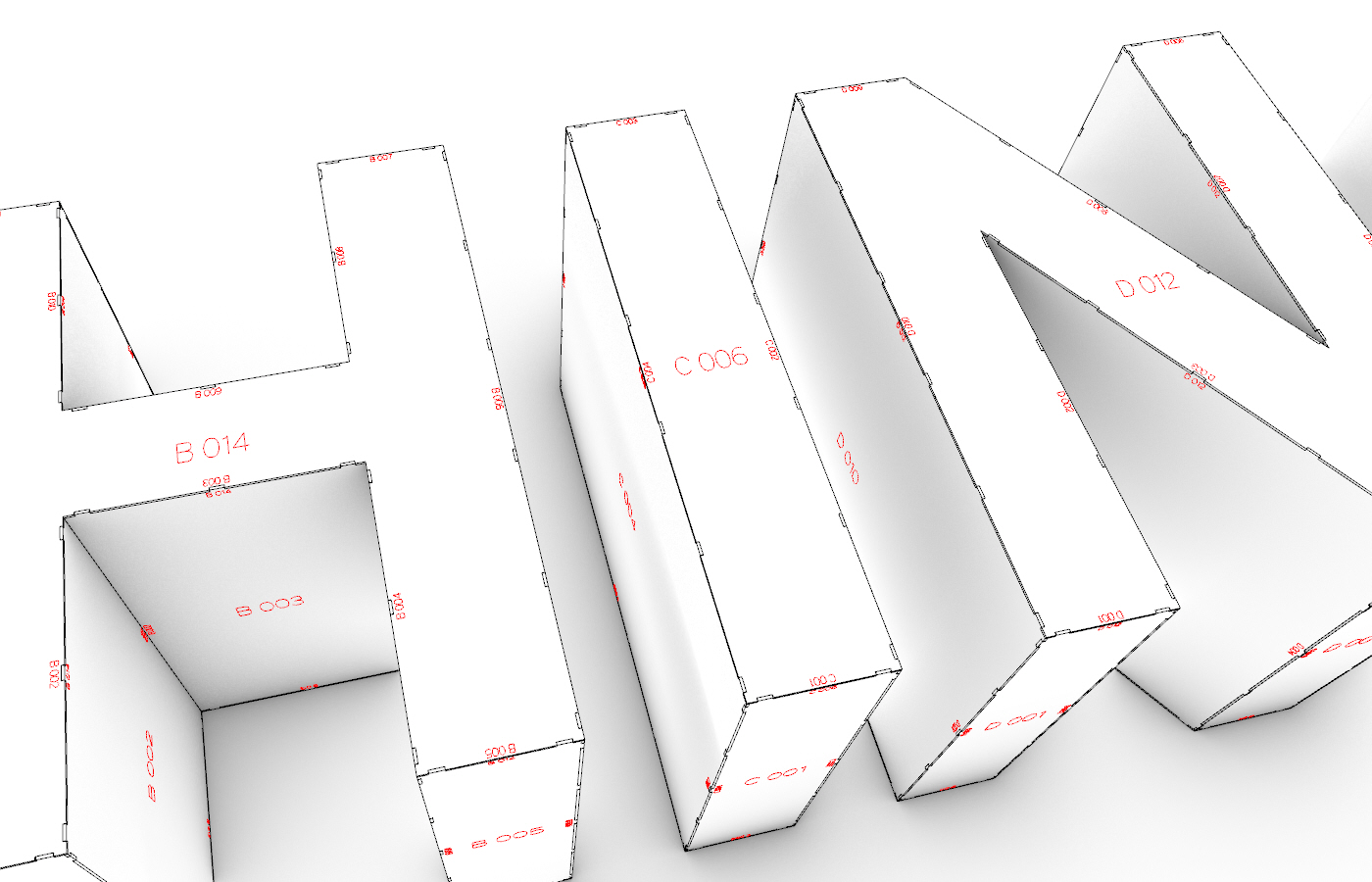
Detail of the letters H, I and N with part labels B 014, C 006 and D 012 and smaller partner numbers at the joint edges.
03 · Assignment in detail: B 014, C 006 and D 012 combine the group letter and part number. The smaller partner numbers along the edges identify the corresponding mating parts.
06Sheet layout & custom presetsReuse formats and settings
  1. Under “Blechbelegung”, select a format or enter the width and height.
  2. Set the sheet margin and part spacing. If appropriate, allow 90° rotations and optimise the layout.
  3. Update and check the number of sheets, utilisation and oversize warnings.
  4. In the relevant section, open “Eigene Vorlagen”, choose “Neue Vorlage”, enter a name and save.
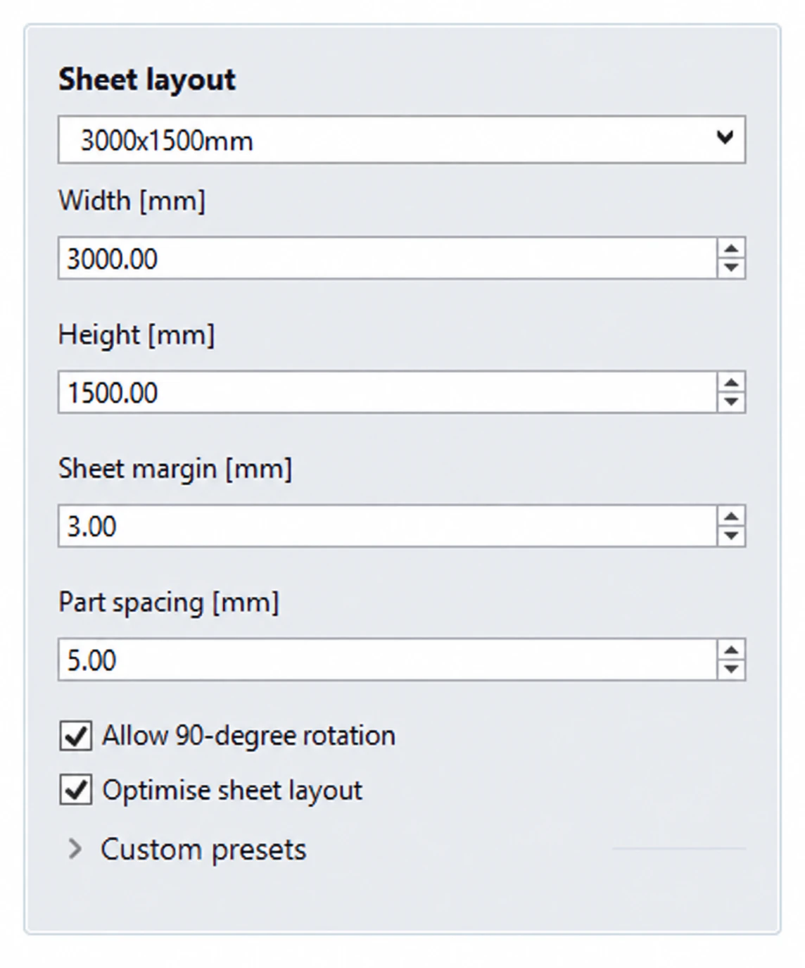
Translated illustration: RhinoLaser sheet layout with a 3000 by 1500 mm sheet format, 3 mm sheet margin and 5 mm part spacing; 90-degree rotation and optimisation are enabled.
Translated illustration Set up the sheet layoutFormat shown: 3000 × 1500 mm, with a 3 mm sheet margin and 5 mm part spacing. 90° rotations and layout optimisation are enabled.

Important: Material, joint and sheet presets are separate. The layout tool compares a limited set of arrangements; it does not guarantee a mathematical optimum. Oversized parts are not scaled down automatically.
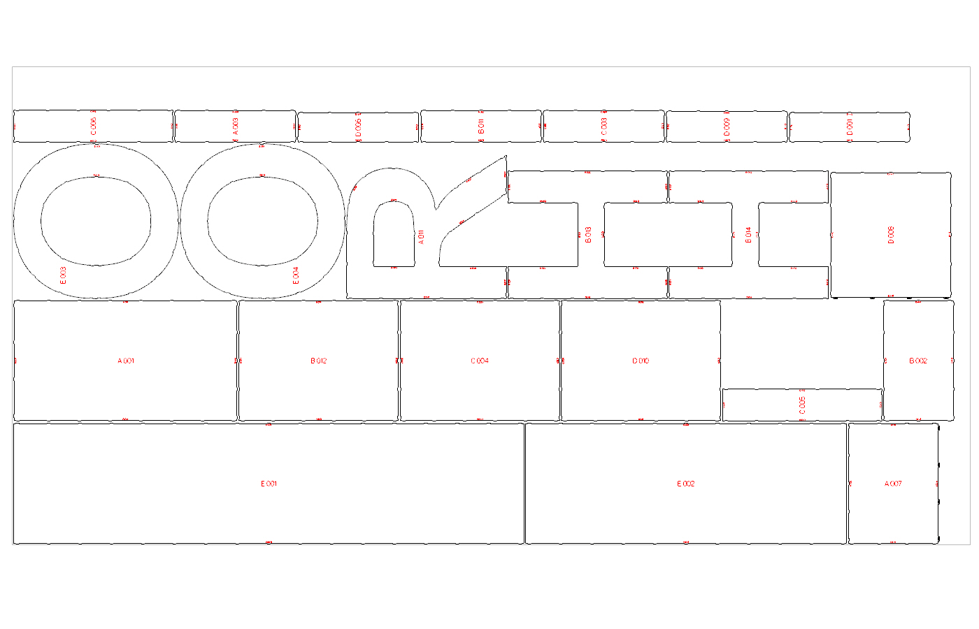
Flat cut parts for the RHINO lettering arranged on a rectangular sheet, with black contours and red part and partner numbers from groups A to E.
Sheet layout result: flat cut parts on one sheet. Group labels are retained even when parts are rotated or placed next to parts from other groups.
07Sheet divisions & split edgesDefine where a sheet-metal part ends
  1. Choose “Geeignete Flaechen automatisch verbinden” or keep the existing divisions. The default transition angle is 2°.
  2. Choose “Trennkanten festlegen ...”, click the desired edges on the original model and confirm.
  3. For an additional split, draw a suitable curve on the source surface, use “Zusaetzliche Trennkurve waehlen ...” and identify the corresponding source solid.
  4. Generate or update the output. Check the split specifications marked in magenta and the opening seams marked in orange.

Check: The splitting curve fully divides the surface. A closed shell requires an opening seam.

New in development build 0.20.6: “Kanten durchgehend verbinden ...” marks suitable shared Brep/extrusion edges in green, including those between separate source objects. Both partners must be selected. Combining this with internal sheets still requires further testing.
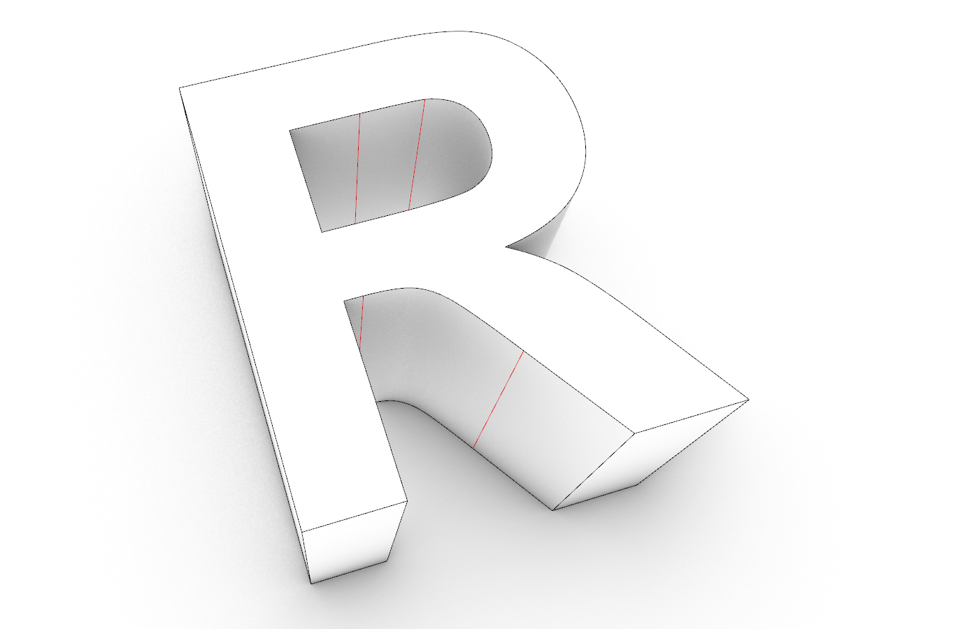
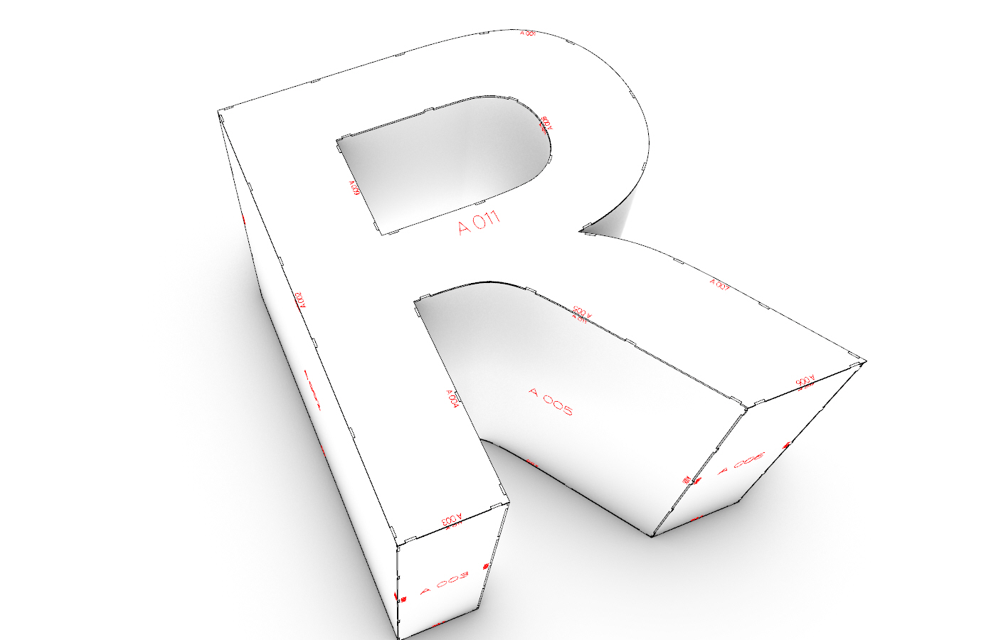
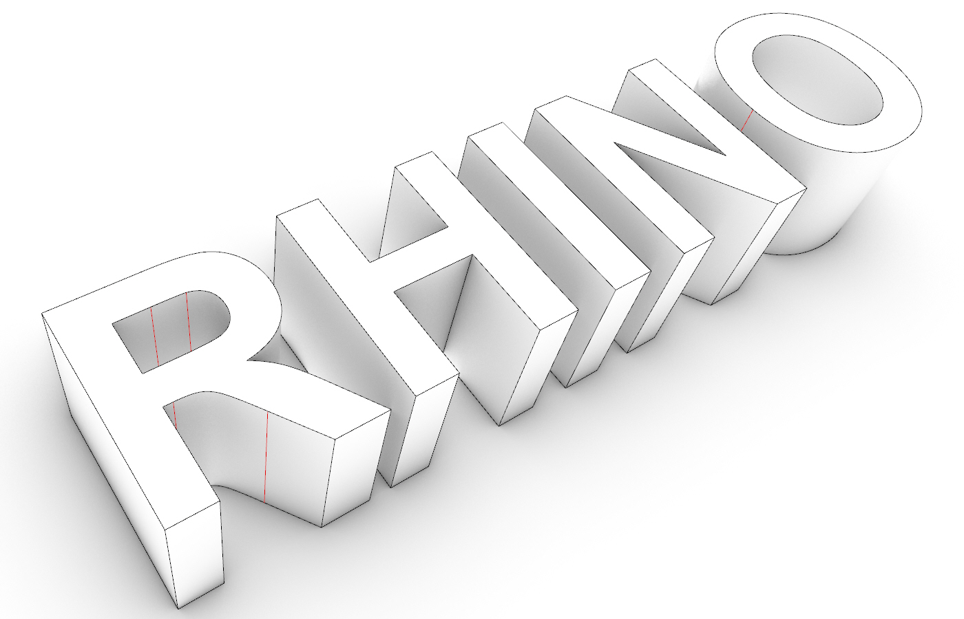
Letter R before merging suitable surfaces. Red lines in the image mark divisions between sheet-metal parts that have not yet been merged.
Before: divisions between sheet-metal parts that have not yet been merged are marked in red on the letter R.
Letter R after merging suitable surfaces: the previously red-marked divisions have disappeared within the merged sheets; red part and partner numbers are visible.
After: suitable surfaces have been merged into continuous sheet-metal parts. The previously red-marked divisions are removed here; the output shows part and partner numbers.
08Curved sheets & internal sheetsCheck advanced geometry carefully
  1. Start with a simple, suitable extrusion or strip surface and enable “Gekruemmte Bleche zulassen”.
  2. Check the material thickness and the orientation of the original surface. For native unrolling, use “Kantenstoß” or a suitable rectangular joint, not the tack-welding hole joint.
  3. Enable the 3D material preview for additional spot checks of material and contact.
  4. Generate the output and review joint errors, inner length deviation and stretching/compression.
  5. For internal sheets, select a suitable multi-surface outer shell and separate individual surfaces together. Enable the centred internal-sheet mode and check rectangular joints individually.

Limitations: Native unrolling uses the middle material layer with K = 0.5. Not every freeform surface can be flattened without distortion. Do not combine new green connection edges with internal sheets without checking them.

09Check, export & keep workingHand over a traceable result
  1. Under “Ergebnis & Export”, read the overview and all notices. Check unusual parts, missing engravings and oversized parts.
  2. Set “Gravur mit exportieren” as needed and choose “DXF exportieren...”.
  3. Select the parent destination folder. RhinoLaser creates a new subfolder containing one DXF per sheet and additional reports.
  4. If needed, choose “Kalkulation als PDF...” separately. In the manufacturing software, correctly assign millimetres, CUT and ENGRAVE.
  5. Save the Rhino file as a 3DM. Later, choose “Vorhandene Ausgabe ansehen” and “Ausgabe laden”, then click an object belonging to that output.
  6. Change settings and update the intended output. Manually modified cutting or engraving objects may prevent export and updates.

Check: Geometry, numbers and reports come from the same checked state. Being able to export does not, by itself, mean the result is approved for manufacturing.

05 / GOOD TO KNOW

Clear answers.
Clear limitations.

What RhinoLaser handles – and what remains your responsibility before manufacturing.

Which Rhino version is supported?

The documented package build is set up for Rhino 7 on Windows. Rhino 8 and macOS are not confirmed here as approved platforms. Follow the installation instructions supplied with the relevant released version.

Can I unroll any 3D model?

Suitable surfaces, polysurfaces, solids, meshes and block instances can be used as inputs. The geometry must produce supported contours and joints. Arbitrary doubly curved freeform surfaces cannot be flattened into sheet metal without deformation. Experimental freeform modules are not yet standard tools in the user interface.

Will my original model be changed?

The calculation processes copies and creates results on separate output layers. The original is not replaced by the cut parts. Saved outputs can be reopened in the Rhino document and updated individually.

Why is an engraving missing from a part?

The part's own number is placed first and reduced in size if needed. If there is not enough room even at a height of 3 mm, it is omitted and reported. This avoids placing unsuitable labels across cutting edges or cutouts.

Do weight and cut length amount to a price calculation?

They provide a basis for costing. Area, volume, weight, and cutting, engraving and weld-edge lengths are calculated geometrically. Prices, setup costs, machine times and quotations are not calculated automatically.

Is the DXF automatically ready for every laser machine?

The DXF contains geometry in millimetres on CUT and, optionally, ENGRAVE. Operations, kerf and machine parameters must be set appropriately in the manufacturing software. Warnings and oversized parts may remain even when the result can be exported. The preview and check reports do not replace a pre-manufacturing review.

FROM YOUR FIRST BOX TO YOUR OWN PROJECT
Your next connection
starts with your model.

Start with the box